v Question NO 1
Discuss topologies in detail?
v Explanation:-
1. Ring Topology:
2. Bus (Line) Topology
3.
Star Topology
4. Tree Topology
5. Mesh Topology
6.
Extended Star
Topology
7. Hierarchical Topology
Network
topology is the name given to the way in which the devices (called nodes) are
physically connected in a network.
There are common network topologies,
called Ring, Bus , Star, Tree, Mesh etc...
You will be expected to briefly describe the
features of each one, know their advantages and draw simple line diagrams to
represent then.
1. RING TOPOLOGY:
Network
cabling scheme in which one cable sequentially connects all nodes and forms a
closed loop. A data packet starting from the originating node is examined by
the next active node if it is addressed to that node. If it does, it is copied,
otherwise it is regenerated and passed on to the next node until it reaches back
the originating node and is discarded. The ability to regenerate data packets
allows a ring topology to span far greater distance than bus or star
topologies.

Advantages:
- Not greatly affected by adding further nodes or heavy
network traffic as only the node with the 'token' can transmit data so
there are no data collisions.
- Relatively cheap to install and expand.
Disadvantages:
- Slower than a star topology under normal load.
- If the cable fails anywhere in the ring then the whole
network will fail.
- If any node fails then the token cannot be passed
around the ring any longer so the whole network fails...
- The hardest topology to troubleshoot because it can be
hard to track down where in the ring the failure has occurred.
- Harder to modify or expand because to add or remove a
node you must shut down the network temporarily.
- In order for the nodes to communicate with each other they must all be switched on.
2. BUS
(LINE) TOPOLOGY:
Network cabling scheme in which all
computers and devices (nodes) are connected to a single cable
so that all nodes receive the same message at the same
time. Also called bus network.

Advantages:
- The simplest and cheapest to install and extend.
- Well suited for temporary networks with not many nodes.
- Very flexible as nodes can be attached or detached
without disturbing the rest of the network.
- Failure of one node does not affect the rest of the bus
network.
- Simpler than a ring topology to troubleshoot if there
is a cable failure because sections can be isolated and tested
independently.
Disadvantages:
- If the bus cable fails then the whole network will
fail.
- Performance of the network slows down rapidly with more
nodes or heavy network traffic.
- The bus cable has a limited length and must be
terminated properly at both ends to prevent reflected signals.
- Slower than a ring network as data cannot be
transmitted while the bus is in use by other nodes.
3. STAR
TOPOLOGY:
Network cabling scheme in which all nodes are
individually connected to a central hub, failure of which will cause the entire
network to shut down. Also called star network

Advantages:
- The most reliable because the failure of a node or a
node cable does not affect other nodes.
- Simple to troubleshoot because only one node is
affected by a cable break between the switch and the node.
- Adding further nodes does not greatly affect
performance because the data does not pass through unnecessary nodes.
- Easily upgraded from a hub to a switch or
with with a higher performance switch.
- Easy to install and to expand with extra nodes.
Disadvantages:
- Uses the most cable which makes it more expensive to
install than the other two topologies.
- The extra hardware required such as hubs or switches
further increases the cost.
- As the central computer controls the whole system, the
whole system will be affected if it breaks down or if the cable link
between it and the switch fails.
- If the switch, the link to the server or the server itself fails then the whole network fails.
4.
TREE TOPOLOGY:
Tree
topologies integrate multiple star topologies together onto a bus. In its
simplest form, only hub devices connect directly to the tree bus, and each hub
functions as the root of a tree of devices. This bus/star hybrid approach
supports future expandability of the network much better than a bus (limited in
the number of devices due to the broadcast traffic it generates) or a star
(limited by the number of hub connection points) alone.

5. MESH TOPOLOGY:
Mesh topologies
involve the concept of routes. Unlike each of the previous topologies, messages
sent on a mesh network can take any of several possible paths from source to
destination. (Recall that even in a ring, although two cable paths exist,
messages can only travel in one direction.) Some WANs, most notably the
Internet, employ mesh routing.
A mesh network in which every
device connects to every other is called a full mesh. As shown in the
illustration below, partial mesh networks also exist in which some devices
connect only indirectly to others.

6.
EXTENDED STAR TOPOLOGY:
Uses the star topology to be created. It links individual
stars together by linking the hubs/ switches. This will extend the length of
the network.

7.
HIERARCHICAL TOPOLOGY:
Is created similar to an extended star but
instead of linking the hubs/ switches together, the system is linked to a
computer that controls the traffic on the topology.

SUMMARY
Topologies remain an important part of
network design theory. You can probably build a home or small business computer
network without understanding the difference between a bus design and a star
design, but becoming familiar with the standard topologies gives you a better
understanding of important networking concepts like hubs, broadcasts, and
routes.
v Question NO 2
Define network devices and on which
OSI layer they are working?
v Explanation:-
Network
devices are components used to connect computers or other electronic devices
together so that they can share files or resources like printers
or fax machines. Devices used to setup a Local Area Network (LAN) are
the most common type of network devices used by the public. A LAN requires a
hub, router, cabling or radio technology, network cards, and if online
access is desired, a high-speed modem. Happily this is much less complicated
than it might sound to someone new to networking.
1)
HUB
Networks
using a Star topology require a central point for the devices to connect.
Originally this device was called a concentrator since it consolidated the
cable runs from all network devices. The basic form of concentrator is the hub.

As
shown in Figure; the hub is a hardware device that contains multiple;
independent ports that match the cable type of the network. Most common hubs
interconnect Category 3 or 5 twisted-pair cable with RJ-45 ends, although Coax
BNC and Fiber Optic BNC hubs also exist. The hub is considered the least common
denominator in device concentrators. Hubs offer an inexpensive option for
transporting data between devices, but hubs don't offer any form of
intelligence. Hubs can be active or passive.
An active hub strengthens and
regenerates the incoming signals before sending the data on to its destination.
Passive hubs do nothing with
the signal.
2)
Ethernet
Hubs
 An
Ethernet hub is also called a multiport repeater. A repeater is a device that
amplifies a signal as it passes through it, to counteract the effects of
attenuation. If, for example, you have a thin Ethernet network with a cable
segment longer than the prescribed maximum of 185 meters, you can install a
repeater at some point in the segment to strengthen the signals and increase
the maximum segment length. This type of repeater only has two BNC connectors,
and is rarely seen these days.
An
Ethernet hub is also called a multiport repeater. A repeater is a device that
amplifies a signal as it passes through it, to counteract the effects of
attenuation. If, for example, you have a thin Ethernet network with a cable
segment longer than the prescribed maximum of 185 meters, you can install a
repeater at some point in the segment to strengthen the signals and increase
the maximum segment length. This type of repeater only has two BNC connectors,
and is rarely seen these days.
3)
8
Port mini Ethernet Hub
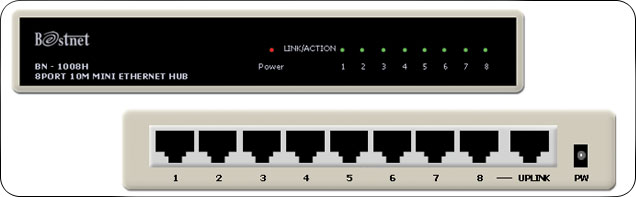 The
hubs used on UTP Ethernet networks are repeaters as well, but they can have
many RJ45 ports instead of just two BNC connectors. When data enters the hub
through any of its ports, the hub amplifies the signal and transmits it out
through all of the other ports. This enables a star network to have a shared
medium, even though each computer has its own separate cable. The hub relays
every packet transmitted by any computer on the network to all of the other
computers, and also amplifies the signals.
The
maximum segment length for a UTP cable on an Ethernet network is 100 meters. A
segment is defined as the distance between two communicating computers.
However, because the hub also functions as a repeater, each of the cables
connecting a computer to a hub port can be up to 100 meters long, allowing a
segment length of up to 200 meters when one hub is inserted in the network.
4)
Multi-station Access Unit
 A Multi-station Access Unit (MAU) is
a special type of hub used for token ring networks. The word "hub" is used most
often in relation to Ethernet networks, and MAU only refers to token ring
networks. On the outside, the MAU looks like a hub. It connects to multiple
network devices, each with a separate cable.
A Multi-station Access Unit (MAU) is
a special type of hub used for token ring networks. The word "hub" is used most
often in relation to Ethernet networks, and MAU only refers to token ring
networks. On the outside, the MAU looks like a hub. It connects to multiple
network devices, each with a separate cable.
Unlike a hub that uses a logical bus topology over a physical star, the
MAU uses a logical ring topology over a physical star.
ring topology over
a physical star.
When the MAU detects a problem with a
connection, the ring will beacon. Because it uses a physical star topology, the
MAU can easily detect which port the problem exists on and close the port, or
"wrap" it. The MAU does actively regenerate signals as it transmits
data around the ring.
5) Switches
 Switches are a special type of hub that
offers an additional layer of intelligence to basic, physical-layer repeater
hubs. A switch must be able to read the MAC address of each frame it receives.
This information allows switches to repeat incoming data frames only to the
computer or computers to which a frame is addressed. This speeds up the network
and reduces congestion.
Switches are a special type of hub that
offers an additional layer of intelligence to basic, physical-layer repeater
hubs. A switch must be able to read the MAC address of each frame it receives.
This information allows switches to repeat incoming data frames only to the
computer or computers to which a frame is addressed. This speeds up the network
and reduces congestion.
Switches operate at
both the physical layer and the data link layer of the OSI Model.
6)
Bridges

Bridges can also
connect networks that run at different speeds, different topologies, or
different protocols. But they cannot, join an Ethernet segment with a Token
Ring segment, because these use different networking standards. Bridges operate
at both the Physical Layer and the MAC sub layer of the Data Link layer.
Bridges read the MAC header of each frame to determine on which side of the
bridge the destination device is located, the bridge then repeats the
transmission to the segment where the device is located.
7)
Routers
 Routers Are
networking devices used to extend or segment networks by forwarding packets from
one logical network to another. Routers are most often used in large
internetworks that use the TCP/IP protocol suite and for connecting TCP/IP
hosts and local area networks (LANs) to the Internet using dedicated leased
lines.
Routers Are
networking devices used to extend or segment networks by forwarding packets from
one logical network to another. Routers are most often used in large
internetworks that use the TCP/IP protocol suite and for connecting TCP/IP
hosts and local area networks (LANs) to the Internet using dedicated leased
lines.
Routers work at the
network layer (layer 3) of the Open Systems Interconnection (OSI) reference
model for networking to move packets between networks using their logical
addresses (which, in the case of TCP/IP, are the IP addresses of destination
hosts on the network). Because routers operate at a higher OSI level than
bridges do, they have better packet-routing and filtering capabilities and
greater processing power, which results in routers costing more than bridges.
8) NICs
(Network Interface Card)
 Network Interface Card, or NIC is a hardware
card installed in a computer so it can communicate on a network. The network
adapter provides one or more ports for the network cable to connect to, and it
transmits and receives data onto the network cable.
Network Interface Card, or NIC is a hardware
card installed in a computer so it can communicate on a network. The network
adapter provides one or more ports for the network cable to connect to, and it
transmits and receives data onto the network cable.
9) Wireless
Lan card
Every networked computer must also have a network adapter driver, which controls the network adapter. Each network adapter driver is configured to run with a certain type of network adapter.
10) Network
Card
 Network Interface
Adapter Functions
Network Interface
Adapter Functions Network interface adapters perform a variety of functions that are crucial to getting data to and from the computer over the network.
These functions are as follows:
i.
Data
encapsulation
The network interface adapter and its
driver are responsible for building the frame around the data generated by the
network layer protocol, in preparation for transmission. The network interface
adapter also reads the contents of incoming frames and passes the data to the
appropriate network layer protocol.
ii.
Signal
encoding and decoding
The network interface adapter implements the
physical layer encoding scheme that converts the binary data generated by the
network layer-now encapsulated in the frame-into electrical voltages, light
pulses, or whatever other signal type the network medium uses, and converts
received signals to binary data for use by the network layer.
iii.
Transmission
and reception
The primary function of the network
interface adapter is to generate and transmit signals of the appropriate type
over the network and to receive incoming signals. The nature of the signals
depends on the network medium and the data-link layer protocol. On a typical
LAN, every computer receives all of the packets transmitted over the network,
and the network interface adapter examines the destination address in each
packet, to see if it is intended for that computer. If so, the network
interface adapter passes the packet to the computer for processing by the next
layer in the protocol stack; if not, the network interface adapter discards the
packet.
iv.
Data
buffering
Network interface adapters transmit and
receive data one frame at a time, so they have built-in buffers that enable
them to store data arriving either from the computer or from the network until
a frame is complete and ready for processing.
v.
Serial/parallel
conversion
The communication between the computer and
the network interface adapter runs in parallel, that is, either 16 or 32 bits
at a time, depending on the bus the adapter uses. Network communications, however,
are serial (running one bit at a time), so the network interface adapter is
responsible for performing the conversion between the two types of
transmissions.
vi.
Media
access control
The
network interface adapter also implements the MAC mechanism that the data-link
layer protocol uses to regulate access to the network medium. The nature of the
MAC mechanism depends on the protocol used.

vii.
WAPs (Wireless Access Point)
A wireless network adapter card with a
transceiver sometimes called an access point, broadcasts and receives signals
to and from the surrounding computers and passes back and forth between the
wireless computers and the cabled network.
Access points act as wireless hubs to link
multiple wireless NICs into a single subnet. Access points also have at least
one fixed Ethernet port to allow the wireless network to be bridged to a
traditional wired Ethernet network.
√ LAYERS IN THE OSI
MODEL OF A COMPUTER NETWORK
The OSI
(Open System Interconnection) Model breaks the various aspects of a computer
network into seven distinct layers. Each successive layer envelops the layer
beneath it, hiding its details from the levels above.
The OSI Model isn't itself a networking
standard in the same sense that Ethernet and TCP/IP are. Rather, the OSI Model
is a framework into which the various networking standards can fit. The OSI
Model specifies what aspects of a network's operation can be addressed by
various network standards. So, in a sense, the OSI Model is sort of a
standard's standard.

The first three layers are sometimes called
the lower layers. They deal with the mechanics of how
information is sent from one computer to another over a network. Layers 4–7 are
sometimes called the upper layers. They deal with how
applications relate to the network through application programming interfaces.
Layer 1: The Physical Layer
The bottom layer of the OSI Model is the
Physical Layer. It addresses the physical characteristics of the network, such
as the types of cables used to connect devices, the types of connectors used,
how long the cables can be, and so on. For example, the Ethernet standard for
100BaseT cable specifies the electrical characteristics of the twisted-pair cables,
the size and shape of the connectors, the maximum length of the cables, and so
on.
Another aspect of the Physical Layer is that
it specifies the electrical characteristics of the signals used to transmit
data over cables from one network node to another. The Physical Layer doesn't
define any particular meaning for those signals other than the basic binary
values 0 and 1. The higher levels of the OSI model must assign meanings to the
bits transmitted at the Physical Layer.
One type of Physical Layer device commonly
used in networks is a repeater. A repeater is used to
regenerate signals when you need to exceed the cable length allowed by the
Physical Layer standard or when you need to redistribute a signal from one
cable onto two or more cables.
An old-style 10BaseT hub is also a Physical
Layer device. Technically, a hub is a multi-port repeater because
its purpose is to regenerate every signal received on any port on all the hub's
other ports. Repeaters and hubs don't examine the contents of the signals that
they regenerate. If they did, they'd be working at the Data Link Layer, not at
the Physical Layer.
Layer 2: The Data Link Layer
The Data Link Layer is the
lowest layer at which meaning is assigned to the bits that are transmitted over
the network. Data-link protocols address things, such as the size of each
packet of data to be sent, a means of addressing each packet so that it's
delivered to the intended recipient, and a way to ensure that two or more nodes
don't try to transmit data on the network at the same time.
The Data Link Layer also provides basic error
detection and correction to ensure that the data sent is the same as the data
received. If an uncorrectable error occurs, the data-link standard must specify
how the node is to be informed of the error so it can retransmit the data.
At the Data Link Layer, each device on the
network has an address known as the Media Access Control address, or MAC
address. This is the actual hardware address, assigned to the device
at the factory.
You can see the MAC address for a computer's
network adapter by opening a command window and running the ipconfig
/all command.
Layer 3: The Network Layer
The Network Layer handles
the task of routing network messages from one computer to another. The two most
popular Layer-3 protocols are IP (which is usually paired with TCP) and IPX
(normally paired with SPX for use with Novell and Windows networks).
One important function of the Network Layer
is logical addressing. Every network device has a physical
address called a MAC address, which is assigned to the device
at the factory. When you buy a network interface card to install in a computer,
the MAC address of that card can't be changed. But what if you want to use some
other addressing scheme to refer to the computers and other devices on your
network? This is where the concept of logical addressing comes in; a logical
address gives a network device a place where it can be accessed on the network -
using an address that you assign.
Logical addresses are created and used by Network
Layer protocols, such as IP or IPX. The Network Layer protocol translates
logical addresses to MAC addresses. For example, if you use IP as the Network
Layer protocol, devices on the network are assigned IP addresses, such as
207.120.67.30. Because the IP protocol must use a Data Link Layer protocol to
actually send packets to devices, IP must know how to translate the IP address
of a device into the correct MAC address for the device. You can use
the ipconfig command to see the IP address of your computer.
Another important function of the Network
layer is routing — finding an appropriate path through the
network. Routing comes into play when a computer on one network needs to send a
packet to a computer on another network. In this case, a Network Layer device
called a router forwards the packet to the destination
network. An important feature of routers is that they can be used to connect
networks that use different Layer-2 protocols. For example, a router can be
used to connect a local-area network that uses Ethernet to a wide-area network
that runs on a different set of low-level protocols, such as T1.
Layer 4: The Transport Layer
The Transport Layer is the basic layer at
which one network computer communicates with another network computer. The Transport
Layer is where you'll find one of the most popular networking protocols: TCP.
The main purpose of the Transport Layer is to ensure that packets move over the
network reliably and without errors. The Transport Layer does this by
establishing connections between network devices, acknowledging the receipt of
packets, and resending packets that aren't received or are corrupted when they
arrive.
In many cases, the Transport Layer protocol
divides large messages into smaller packets that can be sent over the network
efficiently. The Transport Layer protocol reassembles the message on the
receiving end, making sure that all packets contained in a single transmission
are received and no data is lost.
Layer 5: The Session Layer
The Session Layer establishes sessions (instances
of communication and data exchange) between network nodes. A session must be
established before data can be transmitted over the network. The Session Layer
makes sure that these sessions are properly established and maintained.
Layer 6: The Presentation Layer
The Presentation Layer is responsible for
converting the data sent over the network from one type of representation to
another. For example, the Presentation Layer can apply sophisticated
compression techniques so fewer bytes of data are required to represent the
information when it's sent over the network. At the other end of the
transmission, the Transport Layer then uncompressed the data.
The Presentation Layer also can scramble the
data before it's transmitted and then unscramble it at the other end, using a
sophisticated encryption technique.
Layer 7: The Application Layer
The highest layer of the OSI model, the
Application Layer, deals with the techniques that application programs use to
communicate with the network. The name of this layer is a little confusing
because application programs (such as Excel or Word) aren't actually part of
the layer. Rather, the Application Layer represents the level at which
application programs interact with the network, using
programming interfaces to request network services. One of the most commonly
used application layer protocols is HTTP, which stands for Hypertext Transfer Protocol. HTTP is the basis of the World Wide
Web.
v Question NO 3
What is IP and how it works?
v Explanation:-
An Internet
Protocol (IP) address is a numerical identification (logical address) that
is assigned to devices participating in a computer network utilizing the
Internet Protocol for communication between its nodes.[1] Although IP addresses
are stored as binary numbers, they are usually displayed in human-readable
notations, such as 192.168.100.1 (for IPv4), and 2001:db8:0:1234:0:567:1:1 (for
IPv6). The role of the IP address has been characterized as
follows: "A name indicates what we seek. An address indicates where it is.
A route indicates how to get there."

When
you have a protocol, you are sure that all machines one a network (or in the
world, when it comes to the Internet), however different they might be, speak
the 'same language' and can integrate into the whole framework. IP is probably
the most common protocol over the Internet. It is the set of rules governing
how packets are transmitted over the Internet.
v Question NO 4
What are network protocols? What do they do?
Define any 10 network protocols?
v Explanation:-
Sometimes referred to
as an access method, a protocol is
a standard used to define a method of exchanging data over a computer network
such as network, Internet, Intranet, etc. Each protocol has its own
method of how data is formatted when sent and what to do with it once receive,
how that data is compressed or how to check for errors in data.
One of the most common
and known protocols is HTTP (Hypertext Transfer Protocol), which is a
protocol used to transmit data over the world wide web (Internet) TCP/IP, and
SMTP are also network protocols.
Types of Network
Protocols
The most common network
protocols are:
- Ethernet
- Local Talk
- Fast Ethernet
- Token Ring
- FDDI
- ATM
- Gigabit Ethernet
- Transceiver
- Modem
- Brouters
The following is some
common-used network symbols to draw different kinds of network protocols.
i.
Ethernet

The Ethernet protocol
allows for linear bus, star, or tree topologies. Data can be transmitted over
wireless access points, twisted pair, coaxial, or fiber optic cable at a speed
of 10 Mbps up to 1000 Mbps.
ii.
Fast Ethernet
 To allow for an
increased speed of transmission, the Ethernet protocol has developed a new
standard that supports 100 Mbps. This is commonly called Fast Ethernet. Fast
Ethernet requires the use of different, more expensive network
concentrators/hubs and network interface cards. In addition, category 5 twisted
pair or fiber optic cable is necessary. Fast Ethernet is becoming common in
schools that have been recently wired.
To allow for an
increased speed of transmission, the Ethernet protocol has developed a new
standard that supports 100 Mbps. This is commonly called Fast Ethernet. Fast
Ethernet requires the use of different, more expensive network
concentrators/hubs and network interface cards. In addition, category 5 twisted
pair or fiber optic cable is necessary. Fast Ethernet is becoming common in
schools that have been recently wired.iii. Local Talk
Local Talk is a network
protocol that was developed by Apple Computer, Inc. for Macintosh computers.
The method used by Local Talk is called CSMA/CA (Carrier Sense Multiple Access
with Collision Avoidance). It is similar to CSMA/CD except that a computer
signals its intent to transmit before it actually does so. Local Talk adapters
and special twisted pair cable can be used to connect a series of computers
through the serial port. The Macintosh operating system allows the
establishment of a peer-to-peer network without the need for additional software.
With the addition of the server version of AppleShare software, a client/server
network can be established.
The Local Talk protocol
allows for linear bus, star, or tree topologies using twisted pair cable. A
primary disadvantage of Local Talk is speed. Its speed of transmission is only
230 Kbps.
iv.
Token Ring
 The Token Ring protocol
was developed by IBM in the mid-1980s. The access method used involves
token-passing. In Token Ring, the computers are connected so that the signal
travels around the network from one computer to another in a logical ring. A
single electronic token moves around the ring from one computer to the next. If
a computer does not have information to transmit, it simply passes the token on
to the next workstation. If a computer wishes to transmit and receives an empty
token, it attaches data to the token. The token then proceeds around the ring
until it comes to the computer for which the data is meant. At this point, the
data is captured by the receiving computer.
The Token Ring protocol
was developed by IBM in the mid-1980s. The access method used involves
token-passing. In Token Ring, the computers are connected so that the signal
travels around the network from one computer to another in a logical ring. A
single electronic token moves around the ring from one computer to the next. If
a computer does not have information to transmit, it simply passes the token on
to the next workstation. If a computer wishes to transmit and receives an empty
token, it attaches data to the token. The token then proceeds around the ring
until it comes to the computer for which the data is meant. At this point, the
data is captured by the receiving computer. 
The Token Ring protocol requires a star-wired ring using twisted pair or fiber optic cable. It can operate at transmission speeds of 4 Mbps or 16 Mbps. Due to the increasing popularity of Ethernet, the use of Token Ring in school environments has decreased.
v. FDDI
 Fiber Distributed Data
Interface (FDDI) is a network protocol that is used primarily to interconnect
two or more local area networks, often over large distances. The access method
used by FDDI involves token-passing. FDDI uses a dual ring physical topology.
Transmission normally occurs on one of the rings; however, if a break occurs,
the system keeps information moving by automatically using portions of the
second ring to create a new complete ring. A major advantage of FDDI is speed.
It operates over fiber optic cable at 100 Mbps.
Fiber Distributed Data
Interface (FDDI) is a network protocol that is used primarily to interconnect
two or more local area networks, often over large distances. The access method
used by FDDI involves token-passing. FDDI uses a dual ring physical topology.
Transmission normally occurs on one of the rings; however, if a break occurs,
the system keeps information moving by automatically using portions of the
second ring to create a new complete ring. A major advantage of FDDI is speed.
It operates over fiber optic cable at 100 Mbps.
vi.
ATM
 Asynchronous Transfer
Mode (ATM) is a network protocol that transmits data at a speed of 155 Mbps and
higher. ATM works by transmitting all data in small packets of a fixed size;
whereas, other protocols transfer variable length packets. ATM supports a
variety of media such as video, CD-quality audio, and imaging. ATM employs a
star topology, which can work with fiber optic as well as twisted pair cable.
Asynchronous Transfer
Mode (ATM) is a network protocol that transmits data at a speed of 155 Mbps and
higher. ATM works by transmitting all data in small packets of a fixed size;
whereas, other protocols transfer variable length packets. ATM supports a
variety of media such as video, CD-quality audio, and imaging. ATM employs a
star topology, which can work with fiber optic as well as twisted pair cable.
ATM is most often used
to interconnect two or more local area networks. It is also frequently used by
Internet Service Providers to utilize high-speed access to the Internet for
their clients. As ATM technology becomes more cost-effective, it will provide
another solution for constructing faster local area networks.
vii.
Gigabit Ethernet
 The most recent
development in the Ethernet standard is a protocol that has a transmission
speed of 1 Gbps. Gigabit Ethernet is primarily used for backbones on a network
at this time. In the future, it will probably be used for workstation and
server connections also. It can be used with both fiber optic cabling and
copper. The 1000BaseTX, the copper cable used for Gigabit Ethernet, is expected
to become the formal standard in 1999.
The most recent
development in the Ethernet standard is a protocol that has a transmission
speed of 1 Gbps. Gigabit Ethernet is primarily used for backbones on a network
at this time. In the future, it will probably be used for workstation and
server connections also. It can be used with both fiber optic cabling and
copper. The 1000BaseTX, the copper cable used for Gigabit Ethernet, is expected
to become the formal standard in 1999.
viii. Modems

Modems can be external, connected to the computers serial port by an RS-232 cable or internal in one of the computers expansion slots. Modems connect to the phone line using standard telephone RJ-11 connectors.
ix. Transceivers (media converters)

In Ethernet networks, a transceiver is also called a Medium Access Unit (MAU). Media converters interconnect different cable types twisted pair, fiber, and Thin or thick coax, within an existing network. They are often used to connect newer 100-Mbps, Gigabit Ethernet, or ATM equipment to existing networks, which are generally 10BASE-T, 100BASE-T, or a mixture of both. They can also be used in pairs to insert a fiber segment into copper networks to increase cabling distances and enhance immunity to electromagnetic interference (EMI).
x. Brouters
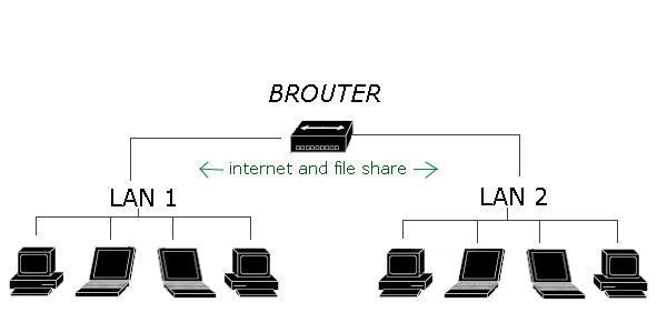 Brouters are a combination of router and bridge. This is a special type of equipment used for networks that can be either bridged or routed, based on the protocols being forwarded. Brouters are complex, fairly expensive pieces of equipment and as such are rarely used.
A Brouter transmits two types of traffic at the exact same time: bridged traffic and routed traffic. For bridged traffic, the Brouter handles the traffic the same way a bridge or switch would, forwarding data based on the physical address of the packet. This makes the bridged traffic fairly fast, but slower than if it were sent directly through a bridge because the Brouter has to determine whether the data packet should be bridged or routed.
v Question NO 5
What Read any two network papers and make summary?
v Explanation:-
Paper No # 01
Title:
High
Data Rate WLAN
Author: Candy Yiu
Department of Computer Science Portland
State University Portland.
Suresh Singh Department of Computer Science
Portland State University Portland.
Published Date and Standard: --------------------
Abstract: This paper considers the problem of providing gbps/user data-rate in
indoor environments.
Summary: This paper describe the technology
uses 60GHz spectrum whose special propagation properties make it ideal when
combined with antenna array technology. They present two algorithms. The first
algorithm is SINR threshold based which uses dynamic spectrum allocation and adaptive
modulation. We show data rates of 2Gbps per user even when 10 users are
present in a small room. The second algorithm dynamically assigns users to channels without using a fixed SINR
threshold. The results show that it can achieve up to 4Gbps/user for the 10
users case. We obtain a bandwidth efficiency of up to 12 b/s/Hz. The experimental results show that the
average data rate falls smoothly when the number of users increase, thus
showing graceful degradation with loading.
Paper No # 02